ASSEMBLY NOTES
Table of Contents
These are just personal study notes. Figured I would share them in case they are useful to someone else. I started writing this in 2019 and returned to it now in 2024 to review the content. Nothing especially origional here, this is just a amalgamation of the documents and tutorials that I read (linked at the bottom).
Terminology:
What is assembly language?
Machine code is the binary representation of the instructions executed directly by the CPU. One level of abstraction above that is assembly language. Assembly language is specific to the CPU architecture. It typically uses mnemonic opcodes to represent operations, such as MOV, ADD, etc.
What is x86-64?
This refers to the 64-bit extension of the x86 instruction set developed for intel processors. x86-64 was introduced in 1999 is the most widely used assembly language for desktops, laptops and servers at time of writing (2024). It supports 64-bit registers, unlike the 32-bit registers for the preceding IA-32 architecture.
What is a register?
The CPU can temporarily store data in registers. They are the fastest storage in the computer (faster than cache or RAM for example) and they are limited in size and count. Some registers are specialised such as the Instruction Pointer which holds the address of the next instruction, or the Stack Pointer which points to the current top of the stack in memory. Others are general purpose.
What is address space?
Address space is the number of addresses in memory that the CPU can access in a single operation. for 64-bit CPUs this is 264 addresses.
Some key features of x86-64:
- 64-bit registers
- Larger address space
- backwards compatibility with 32-bit x68 programs.
- New instructions
- More general purpose registers
- SMID extensions (single instruction, multiple data).
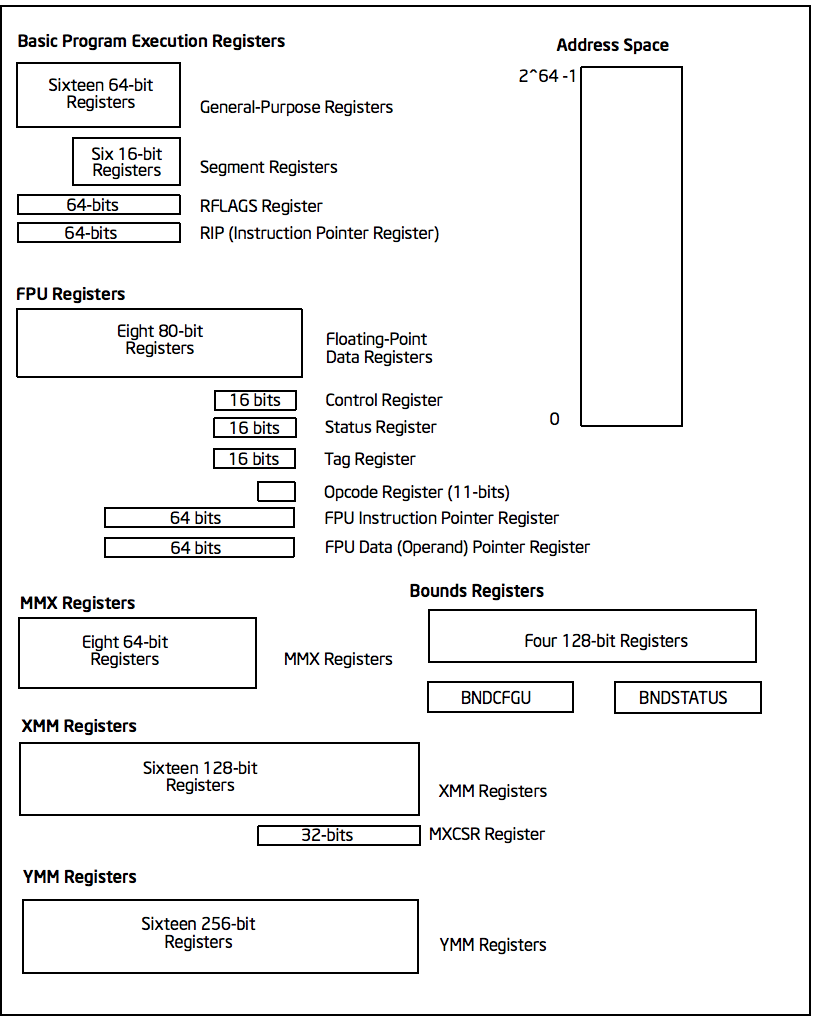
Figure 1: diagram of the x86-64 from Volume 1 of the System Developers Manual
We will get into what some of these registers do below.
Assembly Language
Three Sections
An assembly program has the following three sections: Data, BSS, Text.
data
This denotes the start of the data section of an assembly program:
section .data
This section contains initialized data and constants. Here is an example of a data section:
section .data
    myVariable    db 'Hello, World!',0
    myInteger     dd 12345678h
    myLong        dq 0x123456789ABCDEF0
bss
BSS stands for "block starting symbol". It contains statically allocated variables that have not been assigned values yet. This denotes the beginning of the variable section:
section .bss
The bss section contains variable declarations. Here is an example of a bss section of an x86-64 program.
section .bss
  buffer resb 64           ; Reserve 64 bytes for 'buffer'
  counter resd 1           ; Reserve space for a 4-byte integer (dword) 'counter'
  array resq 10            ; Reserve space for an array of 10 quadwords (64-bit integers)
text
This section contains the actual code.
section .text
  global _start
_start:
Global start lets the kernel know where the program execution begins.
Comments
Comments are preceded with a semicolon. Comments can contain any printable character
; this is a full line comment
add eax, ebx  ; this is an inline comment
Statements
There are three types of statements:
- instructions
These tell the processor what to do.Each instruction has an op-code.
- directives or pseudo-ops
These tell the assembler about the various aspects of the assembly process. These are non-executable.
- macros
Text substitution
Tool-chain
The software tools used in creating assembly programs are as follows:
- Assembler
- Linker
- Loader
- Debugger
Assembler
The assembler is a program converts assembly code into machine language (binary). The output file is known as an object file, hence the .o suffix. During this process the variable names get removed and converted into addresses.
Assembling with NASM
- save the above as a file with extension .asm, for example: hello.asm
- assemble program with:
nasm -f elf hello.asm
- if no errors, hello.o will have been created
- To link the object file and create the executable file named hello:
ld -m elf_i386 -s -o hello hello.o
- execute with:
./hello
Linker
Also known as the linkage editor. This combines object files into a single executable. It also includes any libraries required for execution. The following is a command for the GNU Gold linker:
ld -g -o example example.o
The -g flag tells the linker to include debugging information. The -o flag specifies the output file, here example. Multiple object files can be linked together. When using a function from another file, the function must be flagged with extern.
Dynamic Linking
Linux supports dynamic linking. This allows resolution of some symbols be postponed until the execution of the program. Under Linux dynamically linked object files have the extension .so, shared object. The Windows equivalent is .dll.
Assemble/Link Script
The following is an example of a bash script to automate the calls to the assembler and linker into a single call.
#!/bin/bash

if [ -z $1 ]; then
  echo "Usage: ./asm64 <asmMainFile> (no extension)"
  exit
fi

# verify no extent ions were entered
if [ ! -e "$1.asm" ]; then
  echo "Error, $1.asm not found."
  echo "Note, do not enter file extensions."
  exit
fi

#  Compile, assemble, and link

yasm -Worphan-labels -g dwarf2 -f elf64 $1.asm -l $1.lst ld -g -o $1 $1.o
Loader
This is the part of the operating system that loads the program from secondary storage into memory. Under Linux this is done with the program name. For example, if the program is called hello_world, the command will be:
./hello_world
Debugger
This is a program that can control the execution of the assembly program in order to inspect how it is (or is not) working.
GDB
GDB is a debugger for assembly language as well as C/C++. It is terminal-based but also can be run in emacs. To start in emacs use m-x gdb or to run in the terminal use:
$ gdb <executable>
Prior to this, compile and link the asm source code so that it can be debugged. For example, in order to do this for myprogram.asm:
$ nasm -g -f elf64 -l myprogram.lst myprogram.asm && ld -g -o myprogram myprogram.o
here -g causes NASM to generate debug information. -f specifies the file format (in this case elf64). -l specifies the lst file to be made. Following the call to NASM, a call is made to the GNU linker ld.
To simplify this process, it is recommended to have a shell script to automate assembling and linking in debug mode:
#!/bin/bash

nasm -g -f elf64 -l $1.lst $1.asm && ld -g -o $1 $1.o
To start the execution of a program in gdb use:
(gdb) start
- GDB commands
Command Action b N breakpoint at line N b fn breakpoint at function fn d N delete breakpoint number N info break list breakpoints r run until breakpoint or error c continue running until breakpoint or error s run next line p var print current value of variable var info registers / i r print names and values of registers info registers eax / i r eax prints register eax x/<data-type> &<name> print contents of memory at name
Syntax of Statements
Assembly language has one statement per line
[label] mnemonic [operands] [; comment]
Fields in the square brackets are optional. There are two basic parts to the instruction - the name (mnemonic) and the operands.For example:
INC COUNT ; increment the variable COUNT

MOV TOTAL ; Transfer the total value 48 into memory variable TOTAL
Assembly Hello World
section .text
  global _start  ; must be declared for linker
_start:
  mov edx,len ; message length
  mov ecx,msg ; message to write
  mov ebx,1   ; file descriptor (stdout)
  mov eax,4   ; system call number (sys_write)
  int 0x80    ; call kernel

  mov eax,1   ; system call number (sys_exit)
  int 0x80    ; call kernel

section .data
msg db 'Hello, world!', 0xa ; string to be printed
en equ $ - msg ; length of the string
Memory Segments
Segmented memory model:
In a segmented memory model the system memory is divided into independent segments. Segments are used to store specific types of data. One segment for instruction codes, one for data elements, etc.
Data segment
Represented by the .data section and the .bss section. The .data section is holds static data that remains unchanged during the course of the program. The .bss section is also for static data. Data here are declared during the course of the program. The .bss section is zero filled prior to execution.
Code segment
Represented by the .text section. Fixed data that stores instruction codes.
Stack
This contains data passed to functions and procedures during the course of a program.
Registers
In order to avoid the slow process of reading and storing data in memory, the processor has temporary storage locations called registers. These can store data elements for processing without having to access memory.
General Registers
- Data
These are used for arithmetic, logic and other operations. They have three different modes of usage:
- As complete 32-bit registers: EAX, EBX, ECX, EDX (RAX RBX RCX RDX for 64 bit registers)
- The lower halves can be used as four 16 bit data registers: AX, BX, CX, DX
- The lower halves of the above 16 bit registers can be used as eight 8-bit registers: AH, AL, BH, BL, CH, CL, DH, DL
......................+AX++Accumulator+
EAX |----------------|---AH---|---AL---|

......................+++++BX++Base++++
EBX |----------------|---BH---|---BL---|

......................+++CX++Counter+++
ECX |----------------|---CH---|---CL---|

......................++++DX++Data+++++
EDX |----------------|---DH---|---DL---|
Although the above are most frequently used, there are in total 16 general purpose 64-bit registers.
64-bit lower 32-bits lower 16-bits lower 8-bits rax eax ax al rbx ebx bx bl rcx ecx cx cl rdx edx dx dl rsi esi si sil rdi edi di dil dbp ebp bp bpl rsp esp sp spl r8 r8d r8w r8b r9 r9d r9w r9b r10 r10d r10w r10b r11 r11d r11w r11b r12 r12d r12w r12b r13 r13d r13w r13b r14 r14d r14w r14b r15 r15d r15w r15b - AX -
Primary Accumulator
I/O for most arithmetic instructions, for example multiplication. One operand is stored in other EAX, AX or AL depending on size.
- BX -
Base
Sometimes used in index addressing.
- CX -
Count
Stores loop counts in various iterative operations
- DX -
Data:
Also used in I/O. Notably when large numbers are involved.
- Pointer Registers
Stores addresses in memory. In 32-bit these are EIP, ESP and EBP. In 16-bit these correspond to IP, SP and BP.
- IP -
Instruction Pointer
Stores the
offset addressof the next instruction to be executed. In combination with theCSregister (CS:IP) gives the full address of the current instruction in code segment.- SP -
Stack Pointer
Provides the offset value in the program stack. In combination with the
SSregister (SS:SP) gives the current position of data or address in the program stack.- BP -
Base Pointer
Helps in referencing the parameter variables passed to a subroutine. The address in
SSin combination with the offset BP gives the location of a parameter. Can also be combined with DI and SI as a base register for special addressing. - IP -
- Index Registers
ESI and EDI in 32-bit, or SI and DI in 16-bit.
- SI -
Source Index
Source index for string operations
- DI -
Destination Index
Destination index for string operations.
- SI -
Control
For comparisons and conditional instructions that control flags.
- OF -
Overflow Flag
Indicates overflow of leftmost bit in a signed math operation
- DF -
Direction Flag
In string comparison operations, indicates left or right direction of movement. 0 for left-to-right and 1 is right-to-left
- IF -
Interrupt Flag
Flags if keyboard or other interrupts are to be ignored or processed. 0 for ignored or 1 for processed.
- TF -
Trap Flag
Allows the processor to work in single step mode for debug purposes.
- SF -
Sign Flag
Indicates the sign of a arithmetic result.
- ZF -
Zero Flag
Indicates whether a result of an arithmetic expression is zero.
- AF -
Auxiliary Carry Flag
Used for specialized arithmetic to carry from bit 3 to bit 4.
- PF -
Parity Flag
Indicates the total number of 1 (on) bits in the result of an arithmetic expression. If even then 0, odd then 1.
- CF -
Carry Flag
Contains the carry from the leftmost bit after an arithmetic operation. It also stores the contents of the last bit of a shift or rotate operation.
| Flag | O | D | I | T | S | Z | A | P | C | |||||||
|---|---|---|---|---|---|---|---|---|---|---|---|---|---|---|---|---|
| Bit | 15 | 14 | 13 | 12 | 11 | 10 | 9 | 8 | 7 | 6 | 5 | 4 | 3 | 2 | 1 | 0 |
Segment Registers
These refer to specific areas defined for data, code and stack.
- CS -
Code Segment
Contains the starting address of the code segment.
- DS -
Data Segment
Contains the starting address of the data segment.
- SS -
Stack Segment
Contains the starting address of the stack segment.
There are additional segment registers: ES, FS, GS.
All memory locations within a segment are relative to the starting address of the segment. Since all segments will start at an address that is evenly divisible by 16 (hex 10) there is always a zero in the rightmost hex digit. This zero is not stored in segment registers.
Example of using registers
section .text
  global _start   ; must be declared for linker (gcc)

_start:           ; tell linker entry point
  mov edx,len     ; message length
  mov ecx,msg     ; message to write
  mov ebx,1       ; file descriptor (stout)
  mov eax,4       ; system call number (sys_write)
  int 0x80        ; call kernel

  mov edx,9       ; message length
  mov ecx,s2      ; message to write
  mov ebx,1       ; file descriptor (stout)
  mov eax,4       ; system call number (sys_write)
  int 0x80        ; call kernel

  mov eax,1       ; system call number (sys_exit)
  int 0x80        ; call

section .data
msg db 'Displaying 9 stars',0xa  ; a message
len equ $ - msg ; length of message
s2 times 9 db '*'
XMM Registers
These are used to support floating point operations and Single Instruction Multiple Data (SMID) Instructions, used in graphics and DSP calculations. These are xmm0 to xmm15.
System Calls
API between the the user space and the system space.
System calls are used by putting the number associated with that call into EAX and the arguments to that system call into other specific registers.
For example, this is the call to exit the program. sys_exit:
mov  eax,1 ; system call number moved into eax
int  0x80   ; call kernel
Here is an example for a syscall that has arguments, sys_write:
mov  edx,4    ; message length
mov  ecx,msg  ; some message that has been defined in the data section
mov  ebx,1    ; file descriptor (1 is for standard out)
mov  eax,4    ; system call number (sys_write)
int  0x80     ; call kernel
All syscalls are listed in /usr/include/asm/unistd.h which can be used to look up their numbers. The following is a table of commonly used system calls with their arguments:
| EAX (number) | Name | EBX | ECX | EDX | ESX | EDI |
| 1 | sysexit | int` | ||||
| 2 | sysfork | struct ptregs | ||||
| 3 | sysread | unsigned`int | char | sizet | ||
| 4 | syswrite | unsigned int` | const char | sizet | ||
| 5 | sysopen | const char* | int | int | ||
| 6 | sysclose | unsigned int |
Instructions
Move
mov <dest>, <src>
; for example

mov ax, 42 ; the integer 42 is put into the 16 bit ax register
mov cl, byte [bvar]  ; into the lower c register, a byte is copied from the address of bvar
mov qword [qvar], rdx ; a quad word from the address of qvar is copied into the 64 bit d register.
- Copies data
- Source and destination cannot both be in memory.
- when copying a double word into a 64 bit register, the upper portion of the register is set to zeros.
Address
The load effective address command lea is used to put the address of a variable into a register.
lea <reg64>, <mem>

; for example
lea rcx, byte [bvar] ; put the location of bvar into the rcx register
Convert
Conversion instructions change a variable from one size to another. Narrowing conversions require no specific instructions since the lower portions of registers are directly accessible.
mov rax, 50
mov byte [bval], al
Widening conversions vary depending on the data types involved.
widening - unsigned
Unsigned numbers only take positive values, therefore when dealing with unsigned numbers the upper part of the memory location or register must be set to zero.
mov al, 50
mov rbx, 0
mov bl, al
There is an instruction especially for performing this: movzx
movzx <dest>, <src>
NB: This does not work when converting a quadword destination with a double word source operand. However, simply using mov in this situation will achieve the desired result since it will set the upper portion of the register or memory location to zeros.
widening - signed
When the data is signed, the upper portion must be set to ether zeros or ones depending on the sign of the number.
movsx <dest>, <src> ;general form, used always except when converting between double and quad word.
movsxd <dest>, <src> ; used then converting from double to quadword
Specific registers also have their own signed widening conversion instructions:
| instruction | use |
|---|---|
| cbw | from byte in al to word in ax |
| cwd | from word in ax to double word in dx:ax |
| cwde | from word in ax to double word in eaxy |
| cdq | from double word in eax to quadword in edx:eax |
| cdqe | from double word in eax to quadword in rax |
| cqo | from quadword in rax to double quadword in rdx:rax |
Arithmetic
Addition
add <dest>, <src> ; this results in: <dest> = <dest> + <src>
Operands must be of the same type. Memory to memory addition cannot use the above. One of the operands must be moved into a register.
; Num1 + Num2 (memory to memory) assuming that both are byte size.
mov  al, byte [Num1]
add  al, byte [Num2]
mov  byte [Ans], al
There is also a command for incriminating a value by 1.
inc <operand>
; for example:
inc rax
; when incriminating an operand in memory, specify the size:
inc byte [bNum]
When the numbers being added will result in a sum greater than the register size of the machine, it is necessary to add with a carry. In this situation the Least Significant Quadword is added with an add instruction, then the Most Significant Quadword is added with an adc (add with carry). The second addition must immediately follow the first so that the carry flag is not altered by anything else.
dquad1  ddq 0x1A000000000000000
dquad2  ddq 0x2C000000000000000
dqsum   ddq 0

; using the declarations above:


mov  rax, qword [dquad1]    ; the first 64 bits of dquad1
mov  rdx, qword [dquad1+8]  ; the last 64 bits of dquad1


add  rax, qword [dquad2]    ; add the first 64 bits of dquad2
adc  rdx, qword [dquad2+8]  ; add with carry the last 64 bits of dquad2

mov qword [dqSum], rax      ; result is put into dqSum
mov qword [dqSum+8], rdx
Subtraction
The subtraction commands are self-explanatory when taken with the above information on addition.
sub <dest>, <src>
dec <operand>
Multiplication
There are different commands for multiplying signed or unsigned integers. Both typically produce double sized results.
- Unsigned Integer Multiplication
The general form is as follows:
mul <src>One of the operands must use an A register (al, ax, eax, rax) depending on size. The result is placed in the A (and possibly D) registers.
size register operand output registers byte al op8 ah, al word ax op16 dx, ax double word eax op32 edx, eax quad word rax op64 rdx, rax For example, if two double words are multiplied, the result will be a quad word in dx:ax
dNumA dd 42000
dNumB dd 73000
Ans   dq 0

; Using the above declarations
; dNumA * dNumB

mov  eax, word [wNumA]
mul  dword [wNumB]    ; result goes to edx:eax
mov  dword [Ans], ax
mov  dword [Ans+2], bx
- Signed Integer multiplication
Signed integer multiplication is more flex able with its operands / sizes. The destination must always be a register.
imul <src>
imul <dest>, <src/imm>
imul <dest>, <src>, <imm>
- When one operand is used then
imulworks likemul, but the operands are interpreted as signed. - If two operands are used then the source and destination values are multiplied and the destination value is overwritten. In this case, the source may be an immediate value, a register or a location in memory. A byte size destination operand is not supported.
- When three operands are used, the last two are multiplied and the product is placed in the destination. The
srcmust not be an immediate value. Theimmmust be an immediate value. The result is truncated to the size of the destination operand. Byte size destination is not supported.
- When one operand is used then
- Integer Division
Division requires that the dividend is larger in data type size than the divisor. It is critical that the dividend is set correctly for division to work. For word, double word and quad word divisions the dividend requires both the
D(for upper) andA(for lower) registers. The divisor can be a memory location or a register, not an intermediate. The result will be placed in theAregister, the remainder will go into ether theah,dx,edxorrdxregisters.Size Dividend registers Divisor result register remainder register Byte ah, al op8 al ah Word dx, ax op16 ax dx Double Word edx, eax op32 eax edx Quad Word rdx, rax op64 rax rdx Signed and unsigned integer division instructions work in the same way but have different instructions.
div <src>  ; unsigned
idiv <src> ; signed

; for example
mov  ax, word [NumA]
mov  dx, 0
mov  bx, 5
div  bx
mov  word [Ans], ax
Logic
;        0101        0101         0101
;        0011        0011         0011         0011
;        ----        ----         ----         ----
; and => 0001  or => 0111  xor => 0110  not => 1100

; &
and <dest>, <src>  ; both cannot be memory
; ||
or <dest>, <src>   ; both cannot be memory
; ^
xor <dest>, <src>   ; both cannot be memory
; ¬
not <op>   ; op cannot be immediate
Shift
; logical shifts
shl <dest>, <imm> ; shift left, imm or cl must between 1 and 64
shl <dest>, cl

shr <dest>, <imm> ; shift right, imm or cl must be between 1 and 64
shr <dest>, cl

; arithmetic shift
sal <dest>, <imm> ; left shift. Zero fills the space made:  0010 -> 0100
sal <dest>, cl


sar <dest>, <imm> ; right shift. Sign bit fills the space made:  1101 -> 1110
sar <dest>, cl
Rotate
Rotations are essentially shifts that put the bits that would be shifted off the end onto the beginning, or vica verca.
rol <dest>, <imm> ; rotate left
rol <dest> cl


ror <dest>, <imm> ; rotate right
ror <dest> cl
; for example:

rol rcx, 32
ror qword [qNum], cl
the imm or the value in the cl register must be between 1 and 64. The destination operand cannot be immediate.
Control instructions
These include structures such as if statements and looping.
Labels
These are targets for jumps. These should start with a letter, and my include numbers, underscores, and should be followed by a colon. In YASM labels are case sensitive.
Unconditional control instructions.
jmp <label> ; moves execution in the program to the label.
Conditional Control Instructions
These are made up of two instructions that must happen one immediately after the other. First there has to be some sort of comparison, then the jump instruction. The comparison will compare two operands and store the result in the rFlag register.
cmp <op1>, <op2> ; operands must be of the same size.
; op1 must not be immediate, op2 may be immediate.
This should be followed by a jump instruction.
je <label>  ; if op1 == op2
jne <label> ; if op1 != op2
jl <label>  ; signed, if op1 < op2
jle <label> ; signed, if op1 <= op2
jg <label>  ; signed, if op1 > op2
jge <label> ; signed, if op1 >= op2
jb <label>  ; unsigned, if op1 < op2
jbe <label> ; unsigned, if op1 <= op2
ja <label>  ; unsigned, if op1 > op2
jae <label> ; unsigned, if op1 >= op2
For example, this is a possible implementation for an if else statement:
; using the following declerations:

  TRUE    equ   1
  FALSE   equ   0
  x       dd    0
  y       dd    0
  ans     dd    0
  errFlag db    FALSE

; -------

  cmp    dword [x], 0    ; compare the contents of x to 0
  je     doElse          ; if eaual go to location deElse
  mov    eax, dword [x]  ; ... the "not equal branch". Put x in eax
  cdq                    ; change dword into qword (prep for division)
  idiv   dword [y]
  mov    dword [ans] eax
  mov    byte [errFlag]
  jmp    skpElse
doElse:
  mov    dword [ans], 0
  mov    byte [errflg], TRUE
skpElse:
Notes for the above example:
- since using signed division
idiv, conversion was required:cdq. ebxwas overwritten.
Conditional jumps can be adjacent. for example:
...
   cmp dword [x], 100
   je  equalsJump
   jl  lessThanJump
   jg  greaterThanJump
...
Jump Range
For the above short jumps the target label must be no more than 128 bytes from the jump call. However, this limit does not apply for the unconditional jump jmp.
Iteration
Iteration commands can be used to make simple loops. For example, the following codeblock shows a loop for summing odd integers within a range:
  lpCnt  dq  15
  sum    dq  0

; using the above declerations:
  mov rcx, qword [1pCnt]  ; loop Counter
  mov rax, 1              ; odd integer counter
sumLoop:
  add qword [sum], rax    ; sum current odd interger
  add rax, 2              ; set next odd integer
  dec rcx                 ; decrement loop cionter
  cmp rcx, 0              ; decrement loop counter
  jne sumLoop
Loop
There is a loop instruction which simplifies iteration. It will automatically decriment the rcx register and perform a comparison to 0, jumping when rcx != 0.
; summing n odd numbers

  mov rcx qword [naxN]   ; loop counter
  mov rax, 1             ; pdd int counter
sumLoop:
  add qword [sum], rax   ; sum current odd int.
  add rax, 2             ; next odd int
  loop sumLoop
Example program using intructions
section .data
  SUCCESS      equ  0
  SYS_exit     equ  60
  n            dd   10
  sumOfSquares dq   0
section .text
global start
_start:
  mov         rbx, 1
  mov         ecx, dword [n]
sumloop:
  mov         rax, rbx
  mul         rax
  add         qword [sumOfSquares], rax
  inc         rbx
  loop        sumLoop
last:
  mov         rax, SYS_exit
  mov         rdi, SUCCESS
  syscall
Calling C libraries
C librries can be called from assembly provided they are compiled together. For example:
extern printf

section .data
  msg: db "Hello World", 0; Zero is used as a null termainator
  fmt: db "%s", 10, 0; printf formatting followed by newline and null terminator

section .text
  global main

main:
  push rbp ; push stack
; Set up params for call to printf
  mov rdi, fmt
  mov rsi, msg
  mov rax, 0
  call printf

  pop rbp ; pop stack
  mov rax, 0 ; exit code 0
  ret ; return
To compile and run the above using NASM and GCC:
$ nasm calling_c.asm -f elf64 -o calling_c.o

$ gcc -g -no-pie -o calling_c calling_c.o

$ ./calling_c
Related Topics
Addressing data in memory
The process through which execution is controlled is called the fetch-decode-execute cycle. The instruction is fetched from memory. The processor can access one or more bytes of memory at a given time.
The processor stores data in reverse-byte sequence.
For example, for hex number 0725H:
In register:
|--07--|--25--|
In memory:
|--25--|--07--|
Memory Hierarchy
| Memory Unit | Example Size | Typical Speed |
|---|---|---|
| Processor Registers | 16 to 64 bit registers | ~ 1 nanosecond |
| Cache Memory | 4 - 8+ Megabytes (L1 and L2) | ~ 5 to 60 nanoseconds |
| Primary Storage (RAM) | 2 - 32 Gigabytes | ~ 100 to 150 nanoseconds |
| Secondary storage (HDD) | 500 Gigabytes to 4+ Terabytes | ~ 3-15 milliseconds |
Integer representation
| size name | size | unsigned range | signed range |
|---|---|---|---|
| byte | 28 | 0 - 255 | -128 - 127 |
| word | 216 | 0 - 65535 | -32,768 - 32767 |
| double word | 232 | 0 - 429497294 | -2147483648 2147483647 |
| quadword | 264 | 0 - 264 -1 | -(263) - 263 -1 |
| double quadword | 2128 | 0 - 2128 -1 | -(2127) - 2127 -1 |
Two's Complement
Signed numbers are often represented in twos complement form. A negative representation of a positive number can be made by flipping the bits and then adding 1. For example:
| 9 | 00001001 |
|---|---|
| step 1 | 11110110 |
| step 2 | 11110111 |
| -9 | 11110111 |